CAN
The Controller Area Network (CAN) protocol is a foundational technology in embedded systems.
It is a broadcast-based, message-oriented protocol.
Today, CAN networks are used in industrial automation, avionics, medical tools, and even consumer technologies such as 3D printing systems.
Designed by Bosch in 1983 to resolve the complexity and cost of wiring in automotive electrical systems (vehicles were interconnected via point-to-point wiring topologies).
The CAN introduced a robust serial communication bus that enables all devices to transmit and receive data over a single shared physical medium without requiring a central host computer (no master). CAN broadcasts data globally across the entire network bus.
This architecture means that nodes can be added to or removed from the bus without needing modifications to the software of the existing nodes.
How do devices know for who is the message
Each transmitted message has a header:
- a unique numerical identifier that specifies the content, meaning, and the priority of the message.
Receiving nodes utilize hardware-level filters to determine whether a broadcasted message relevant to them (significantly reducing CPU processing load).
Physical layer
The Wires (Differential Signaling)
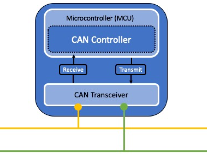
- How it works: CAN uses two twisted wires: CAN High (yellow) and CAN Low (green).
- Why it matters: Instead of looking at absolute voltage, it looks at the difference between the two wires. This makes the system incredibly resistant to electrical noise and interference.
- Backup plan: If one wire breaks, some systems can automatically switch to a “single-wire” mode to keep running.
The Transceiver
- Job: This chip sits between themicrocontroller and the actual network wires. It translates digital 1s and 0s into the physical voltage differences on the wires.
- Protection: It acts as a shield, protecting the fragile microcontroller from massive power surges and static electricity.
- Fail-safe: If a node loses power, the transceiver goes completely passive so it doesn’t drag down or freeze the rest of the network.
Arbitration
Because any node can talk at any time, two or more nodes will eventually try to speak at the exact same moment. To handle this without crashing, CAN uses two types of signals:
- Dominant Bit (0): This is an active electrical signal.
- Recessive Bit (1): This is a passive signal (the node just lets go of the wire).
0 always wins against 1. If Node A transmits a 1 (passive) but Node B transmits a 0 (active), the actual voltage on the wire becomes a 0. The dominant bit physically overwires the recessive bit.
When multiple nodes start talking at the same time, they all start sending their message’s ID number, bit-by-bit. As they send their ID, they also “listen” to the wire to see what is actually happening.
- The Test: Every time a node sends a
1, it checks the wire. If it sees a0instead, it realizes: “Uh oh, someone else is sending a dominant bit right now.”. The node instantly stops talking and switches to listening mode. - The Winner: The node with the lowest numerical ID will naturally have the most zeros (
0s) at the start of its message. Because zeros always win, that node gets to finish its message without a single microsecond of interruption or data corruption.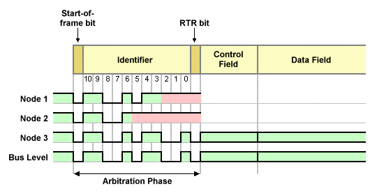
CAN FD
The Problem: Classical CAN is too slow
The original version of the protocol (Classical CAN) has two major limits:
- Tiny Payloads: It can only send a maximum of 8 bytes of data per message.
- Speed Limit: It maxes out at 1 Mbps. It cannot go faster because the “argument resolution” (arbitration) phase requires signals to travel to the end of the wire and back before the next bit is sent.
As modern cars got smarter, they needed to send way more data than 8 bytes at a time could handle.
The Solution: CAN FD (Flexible Data-Rate)
CAN FD fixed this issue by changing two major rules without requiring completely new wiring:
- Bigger Payloads: It boosts the maximum data size from 8 bytes up to 64 bytes per message.
-
The Switch (Dual Bit-Rate): CAN FD literally changes bit-rate mid-message. The diagram below shows exactly how CAN FD changes speed compared to Classical CAN:
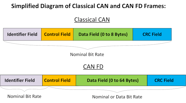 Notice how CAN FD splits its speed based on what the network is doing:
- The Slow Zones: During the Identifier Field (where nodes argue over who gets to talk) and the final check-in, the network runs at the standard, safer Nominal Bit Rate (1 Mbps).
- The Fast Zone: Once a single winner is decided, the CAN FD frame triggers a “Bit Rate Switch.” It shifts into overdrive—speeding up to 8 Mbps—to blast through the larger Data Field and CRC Field before slowing back down.